How to optimize machining of printed circuits? - part 2
.jpg)
In this part of the article on the machining of printed circuits we will describe the most important parameters conditioning the milling time and rules of proper preparation of the process itself. In further part, we will address technics allowing for it optimization. Presented information will allow to reduce machining costs simultaneously maintaining high quality of printed boards.
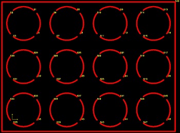
Basic parameter conditioning milling cost is a length of a milling path (pic.1). This is a very simple relation: the longer the path done by the cutter the longer time of the process itself. To shorten it maximally you should avoid doubled passages of the tool on the design stage of the milling course.
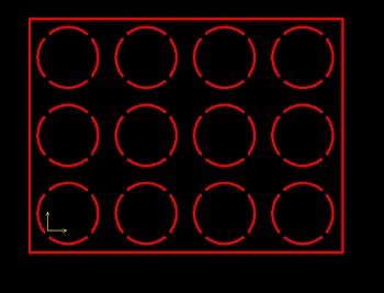
Pic. 1. Milling of the boards in the 270 x 202 mm dimension panel – the path about 2.5 m.
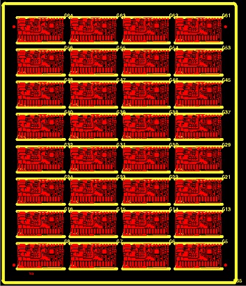
Another parameter influencing the machining time is a number of entrances and exits of the milling tool (pic. 2). This process concerns the number of so called “milling beginnings": the milling machine when finishing cutting one element (e.g. slothole) moves the head to a new point in which another milling will begin. The number of the tool entrances can be easily specified - this is a number of unbroken milling chains made within one circuit or panel.
In case of a big number of the cut-outs the time needed for exit, the head localization changes and entering the laminate again multiplied by the number of the milling beginnings, can exceed the time resulting from the total length of milled edges.
Pic. 2. Number of the milling tool entrances (49 entrances).
The simplest way to shorten the operation time is to prepare machining in such way so the number of a separated chains was as little as possible. This is the task for the circuit designer, he should try to make the cut-outs with one passage of the tool.
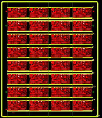
The example of the milling optimization on the way of the chains number reduction is presented on the pic. 3. The panel seen on the picture consists of 32 circuits (8x4 arrangement) which horizontal lines are scored and vertical milled. Originally only sections of the vertical edges (pic. 3a) of the circuits were milled which led to 65 entrances of the cutter into the laminate for each panel. After optimization relaying on milling the edges of the column of all circuits in one pass of the cutter the total number of the entrances of the tool was reduced to 17 so almost 4 times (pic. 3b).
(a)
(b)
Pic. 3. Example of milling optimization – before optimization (a) and after optimization (b).
The other factor influencing the time and quality of milling is the number of used tools. The most often during milling of a single circuit it is necessary to use more than one. This is a result of a different dimensions of cut slotholes and edges as well as types of the cut-outs because cut-outs and slotholes inside the circuit as well as outside shapes of the board (pic. 4) are performed by milling. Although used cutters can have the same diameters they must be made by separate tools due to a different wear compensation.
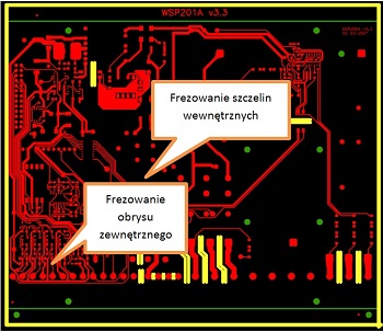
Pic. 4. Internal and external milling.
Cutters during work are wearing which leads to their diameter decrease. Often replacement of tools would multiply machining costs disabling maintaining simultaneously repeatable dimensions especially in a case of a serial production. Modern CNC milling machines have the wear compensation function which relays on a cyclical, laser measurement of the diameter of working tools and adopting the cutter movement path to it real dimension. This means that depending on the cutter moving direction it path is gently shifted once outside and once inside the circuit to finally achieve required final dimension. Additionally, the machine operator after milling and precise measuring of the first circuit has possibility to correct the compensation. Because of this it is necessary to assign other compensation for the internal cut-outs milling and circuit contours milling therefore making them with a different tool.
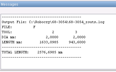
The diameters of the used cutters due to a milling time are essential as well. This is a result of the fact that together with the tools diameter decrease the tool feed speed is decreased and the restriction appears in a possibility to mill a few production formats simultaneously with one tool. Influence of the cutter diameter and corresponding it feed speed on the milling time was shown in the table 1 which shows an example milling time of the 1 m long section for different tools diameters.
|
Tool diameter |
Milling time |
|
0.6 mm |
11 min |
|
1.0 mm |
3.5 min |
|
1.5 mm |
2.5 min |
|
2.0 mm |
2.0 min |
Table 1. Milling time versus tool diameter.
As you can see the time of machining performed with the smallest available tool 0.6 mm and the standard 2.0 mm diameter cutter is moreover five times longer. During the circuit design, it is worth to verify the dimensions of used slotholes and enlarge them maximally allowing for use of the tool of the biggest possible diameter.
The most often the dimension of used tool is resulting from the design of the arcs of a small radius. Standardly used 2.0 mm cutter will leave 1 mm radius arc. If it is necessary to use a smaller arc then properly smaller tool should be used or so called technological undercut should be used. This simple treatment allows to avoid machining with a smaller and more expensive cutter. It relays on the other hand on placing in the circuits corners the non-metalized holes. Such solution allows for using a standard diameter cutter with simultaneous maintaining small radius in the corners (pic. 5).
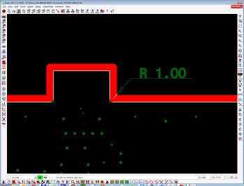
(a)
(b)
Pic. 5. The circuit corners without the undercuts (a) and with use of the undercuts (b).
The minimal diameter of the tool used has a key influence on the milling price so the circuit as well also due to conditioning the number of the laminates which can be milled with the same tool simultaneously in so called package. The smaller the cutter radius the bigger it elasticity and flexibility and what comes with it the bigger probability that the tool will buckle or even break. Dependency of the FR4 laminate number in the package from it thickness and minimal cutter diameter, which is in effect in TS TCB, is presented in the table 2.
|
Cutter min. diameter |
Laminate ≤ 1 mm |
1,0 mm < Laminate < 2 mm |
2 mm ≤ Laminate |
|
cutter ≤ 0,8 mm |
1 format |
1 format |
Not allowed |
|
0,8 mm < cutter ≤ 1,5 mm |
2 formats |
2 formats |
1 format |
|
cutter ≥ 1,5 mm |
4 formats |
3 formats |
2 formats |
Table 2. Number of formats in the package in the cutter diameter and laminate thickness function.
Using the tools of the diameters at least 1.5 mm allows not only for shortening the milling time due to a bigger feed speed but also thanks to a simultaneous milling of 4 formats in the package simultaneously. This means that the time and cost of machining of a bigger batch of circuits can be decreased four times taking into consideration only the number of the formats in the package and twenty times if you additionally consider the differences resulting from the feed speed.
Cutters of the diameter above 1.5 mm maintain proper rigidity and overcome the resistance of the milled FR4 laminate without a problem. In case when it is necessary to make narrow cut-outs and slotholes in circuits you should remember that the cutters making them are more elastic and prone to buckling, especially for the tools of a diameter below 1 mm. As a result of this the cut-out slothole can have smaller than assumed in the project dimension and in an extreme cases also uneven edges (especially for a thicker laminates). This can make assembly of the circuit in the device housing difficult. It is recommended that the tool have the diameter equal or greater than the circuit thickness.
|
|
|
Variant I |
Variant II |
Variant III |
Variant IV |
||||||||||
|
Cutter [mm] |
Feed [m/min] |
Number of entrances |
Path [m] |
Milling time |
Number of entrances |
Path [m] |
Milling time |
Number of entrances |
Path [m] |
Milling time |
Cutter [mm] |
Feed [m/min] |
Number of entrances |
Path [m] |
Milling time |
|
2,0 |
0,4 |
423 |
2,07 |
22 min |
1296 |
2,07 |
48 min |
423 |
4,0 |
29 min |
1,5 |
0,2 |
423 |
2,07 |
31 min |
|
2,0 |
0,4 |
6 |
4,50 |
6 |
4,50 |
6 |
9,0 |
1,0 |
0,2 |
6 |
4,50 |
||||
Table 3. Comparison of influence of a few parameters on the milling time.
The table 3 shows the comparison of influence: of the cutter diameter, path and number of entrances at the milling time of the exemplar project. Variant I is an optimal milling method for which the shortest time was achieved - 22 min. In the variant II the number of the entrances of the first tool was increased which extended the milling time more than twice. The milling path increase with maintain nominal number of the entrances is pictured in the variant III for which the milling time was increased by 7 minutes. The last variant shows the milling time for the tools of a smaller diameter with maintaining nominal path and number of entrances. In this case the milling time will be 31 minutes.
Basing on the data in the table 3 you can say that the best effects of the milling costs optimization by the reduction of it time can be achieved by minimalization of the entrances number of the tool into the laminate therefore using possibly long milling chains. Significant milling time shortening can be achieved also by using the cutters of possibly the biggest diameter.
Summary
In both parts of the article we discussed the issues of machining of printed circuits. We characterized the laminate scoring and milling technics, presented advantages and disadvantages of both methods. In further it part we described in detail milling as a method allowing to achieve almost any external shapes of the circuits as well as the cut-outs inside them. We discussed the most significant parameters conditioning the time and cost consumption of this process. We also proposed a few technics allowing for milling optimization and we gave the guidelines applying which already at the design stage of circuits will help to achieve high quality milling with maintaining the economical price.