
Aluminium core PCBs: parameters, applications and design
Dariusz Załęski Author
The increasing complexity of electronic circuits and their component density on printed circuit boards has begun causing difficulties to engineers and designers in proper dissipation of the head generated in high-power semiconductor components. The standard FR4 glass-reinforced epoxy laminates, high-power components adapted for THT assembly and typical heat sinks significantly raise the production costs, dimensions and weight of devices.
 |
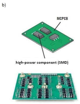 |
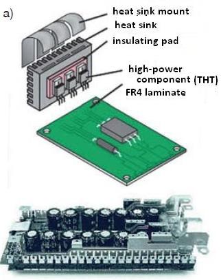
Fig. 1. Comparison of an identical design assembled on (a) the FR4 laminate and (b) the aluminium core.
Using laminates on an IMS (Insulated Metal Substrate) in the form of an aluminium core to manufacture printed circuit boards called MCPCB (Metal Core Printed Circuit Boards) can overcome these problems, or at least greatly reduce them.
Aluminium core laminates are characterised by high thermal conductivity, a parameter designated as TC. The standard IMS laminate offered by PCB manufacturers, including Techno-Service S.A. has the TC at 2 W/mK. There are also commercial material with the TC of 2 to 5 W/mK. The TC of the typical FR4 laminate is one order lower (0.3 W/mK). Moreover, aluminium core laminates are mechanically stronger (more rigid) at the same material thickness and have a thermal expansion lower than FR4.
These advantages make aluminium cores usable as a substrate for PCBs and heat sinks for dissipation of the heat from the assembled SMD components. The benefits of applying IMS laminates, when compared with the traditional FR4, are shown in Fig. 1 that depicts an identical device design assembled in both substrate technologies. The FR4 based device (see Fig. 1a) is much larger and heavier due to the large radiator required for the THT encapsulated power components. It also needs a larger and stronger enclosure. Its production is certainly less cost-effective than the MCPCB version shown in Fig. 1b.
Single-sided MCPCBs are currently most popular on the market. The MCPCB cross-section is shown in Fig. 2. The laminate top side features a traditional conductor layer of copper foil with the thickness analogical to that in FR4 (i.e. 8 μm, 35 μm, 70 μm, 105 μm). The conductive copper layer is separated from the aluminium core by a special dielectric (film) with a high thermal conductivity.
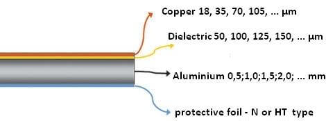
Fig. 2. Build-up of a single-sided aluminium MCPCB and the available thickness values of individual layers.
The dielectric thickness and thermal conductivity determine the TC value and breakdown resistance of the entire laminate. Standard IMS laminates at TC = 2 W/mK feature 125 μm dielectrics which ensure breakdown resistances at singular kV values, which is more than in FR4. The bottom side of the aluminium substrate is coated with a protective foil that keeps the core safe from the damaging action of the chemical solutions applied in PCB manufacturing processes.
The core protective foils is removed at the last production stage. Commercial IMS laminates exist with aluminized cores that are additionally anodised to increase the corrosion resistance of the exposed aluminium face. The added oxide layer inhibits heat dissipation from the core, but the overall reduction of thermal conductivity is small and negligible in the thermal resistance calculations of the circuit for most applications.
Aplications
MCPCBs are popular in modern high power equipment, e.g. pulsed power supply units (inverters) and lamps based on high-output SMD LED arrays. The SMD LED lamps have found general use in lighting applications, the automotive industry (as road lights of motor vehicles) or street signal lights. The laminates for those applications are usually coated with white solder masks that increase light reflectance. Fig. 3 shows examples of MCPCBs for lamps.
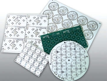
Fig. 3. Examples of MCPCBs produced by Techno-Service.
The costs of aluminium core PCBs mainly depends on the price of the base laminate and its machining. The laminates are relatively hard and require MCPCB manufacturers to operate special tooling. Unlike in FR4, it is also necessary to reduce the milling/routing and scoring feed, and only single production formats can be drilled. Hence the machining of MCPCBs is the highest price driver of the manufacturing costs, and also one of the most time consuming production stages. The processing price can be reduced by:
- Composing the circuits into panels (multi blocks) for scoring;
- Minimizing the surface area for milling/routing and applying square PCBs or panels that can be thoroughly scored;
- Considering the panel design with the working field size of the production format applied by the selected MCPCB manufacturer, since the lowest unit cost per PCB is attained with the maximum usage of the IMS laminate surface. TS PCB applies the working field size of 433×583 mm;
- Using laminates with standard TC values and standard technology offered by the manufacturer. TS PCB has the following technology: single-sided PCBs on laminates at TC = 2 W/mK, 35 μm copper, white solder masks, black text, HAL-plated with a lead-free tin alloy.
The manufacturer’s experience dictates that the best optimisation of MCPCB price is based on the manufacturing costs reduction by strict cooperation between the PCB manufacturer and the customer. This allows defining the optimum design parameters for low execution costs. The manufacturer can offer the best panel arrangement, guide how to reduce the panel production costs and advise on the best materials for specified applications.
Show more from category Quality
-
Quality

Manufacture of printed circuits in harmony with the natural environment - environmental solutions
-
Quality

Manufacture of printed circuits in harmony with the natural environment - recycling
-
Quality

Manufacture of printed circuits in harmony with the natural environment - legal requirements
-
Quality
Manufacture of printed circuits in harmony with the natural environment - waste classification, storage and disposal
-
Quality

Testing printed circuits: AOI optical testing
-
Quality

Testing printed circuits: Blade testers
-
Quality

Testing printed circuits: Finger testing – testing time optimization
-
Quality

Testing printed circuits: Electrical testing – testers with moving probes
-
Quality

Testing printed circuits: Classification of the circuits testing methods and introduction to electrical testing
-
Quality

Base material of printed circuit boards: a few words about laminates
-
Quality

Certificate ISO 9001:2015 and 14001:2015
-
Quality

IPC circuit classes