Integr8tor - problems solving

If operator intervention is required during the analysis of technical documentation, processing in Integr8tor (I8) is stopped and the project is marked as being resolved. After selecting the project, a list of encountered problems is visible (Fig. 1). Some of them are the result of incorrect recognition of layers or stroke detection. They can be solved in the built-in editor, which allows you to manually assign the appropriate type to layers and draw a contour based on drawings of individual layers, or directly enter the dimensions of the tile. However, the vast majority of problems come from weaknesses in the project documentation.
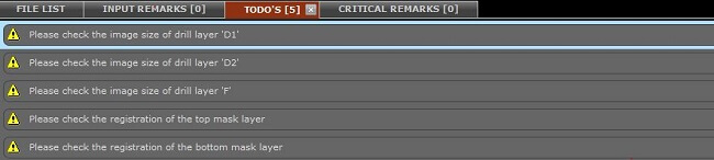
Fig. 1. List of problems resulting from the analysis.
The following is a list of common problems encountered:
- Several project documentation.
When files are uploaded in several files, sometimes in different formats, Integr8tor, like a CAM engineer, is unable to determine which set of files is the right one for production. Always ensure that the documentation is unambiguous and contains all the information you need.
- Files in the RS274D format.
The latest CAM software no longer supports this format. It is worth mentioning that the newer and widely used RS274X version has been in operation for almost 20 years. Transferring files in older formats is becoming increasingly difficult when loading the project into the CAM program. In 2014, another version of the format marked as Gerber X2 was implemented, which contains additional information about the type of layers, thanks to which the process of automated analysis is easier.
- Ambiguous outline.
Problem usually caused by the lack of a circuit outline layer or a partial outline (missing edges). There are also projects with several different outlines or containing several smaller circuits, which have their outlines, but are arranged in a panel with a missing outline. In this case, the program returns a message with an ambiguous outline.
- Problems with layers of drillings.
Usually result from a separate generation of mosaic files and machining files, which are sometimes not included in the documentation due to oversight. Another problem is duplicate drilling files, e.g. with various extensions. These files may have a different structure, although they contain an identical set of holes. Sometimes the drill file does exist, but it lacks the definition of tool diameters. Integr8tor recognises blind and buried blind guides, but it is required to add to the documentation a file defining which layers connect the given hole type (usually with the extension .drr). Metallised and non-metallised holes are also automatically distinguished. It is a good practice to add a drillmap or drill draw file that indicates the location of the holes using unique symbols for individual tool diameters.
- Milling shift.
The most common problem is to move the image relative to the desired position. To prevent this, at the stage of project preparation, you can add reference points on each layer that lie outside the perimeter of the circuit. Thanks to this, the program is able to properly adjust layers in relation to one another.
- The order of internal layers.
I8 usually determines the order of layers according to file extensions, e.g.G1,G2, etc., comments from Gerber files, or it causes searching through other files containing the order e.g. rep, .extrep. If it is not possible to clearly specify the sequence of layers, I8 returns an appropriate message. It is a good habit to specify the order of layers, e.g. on a mechanical layer or in a separate file, or numbering of copper layers on a mosaic of individual files.