TS PCB – towards the Industry 4.0
The enormous development of broadband Internet technology, of wireless communication, together with the increase in the computing power of computers and microsystems, which has been observed for over ten years, has created new opportunities in many areas of life. One of the results are the smart devices that can co – operate with each other via wireless networks (Bluetooth, Wi – Fi) and cable.
These new possibilities have initiated the so – called fourth revolution, leading to the creation of smart factories.
They are characterized by full autonomy of production processes, starting from researching the demand for a specific product on the market, to organizing its production.
The Industry 4.0 phenomenon is particularly visible in the countries of Western Europe (Germany, France, Scandinavian countries), the USA and China. In Poland, the issue of smart factories is still seen as a sort of novelty. The main obstacle to its dissemination is the need to make large investments in the automation and computerization of production, together with the need for the staff specialized in the field of the latest, smart technologies. This current article presents solutions implemented in the company TS PCB – the Polish leader in the production of printed circuits, which in the future will enable it to move to the fourth level.
System integration – from order to shipping
One of the basic assumptions of the Industry 4.0 is integration of various IT systems and architectures in the enterprise into one organism.
These subsystems can communicate not only via ERP, which is the core of the system, but also directly between selected nodes.
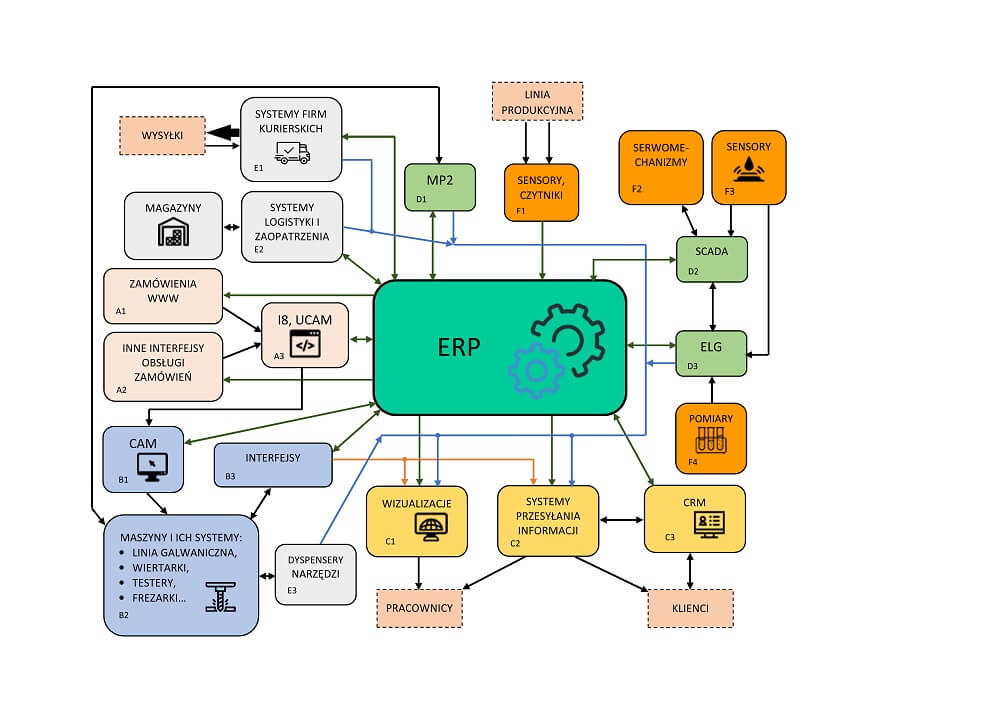
The system integration in the company TS PCB, and the network of connections between its elements are presented in a simplified block diagram (Fig. 1).
Fig. 1. A simplified block diagram of the systems and subsystems.
Individual subsystems are in this diagram marked with blocks in different colours and with letters.
An integral element of the structure is the ERP system, which communicates with the surrounding subsystems thanks to channels represented by dark green arrows. The vast majority of the communication is bi – directional, except for a block of sensors and readers providing information about the position of printed circuits throughout the entire production chain – this is marked F1 in the diagram. The data ix transmitted by cable and wireless.
The production process begins with the handling of orders – it is represented by blocks A1 and A2. The first block is responsible for transmitting orders and offers submitted via the website, and for providing the feedback, including the information about the status of the orders. The A2 block provides flexible communication via the Internet with the customer systems, for the purpose of free and fully automated order transfer, and feedback in the form of registers of ordered circuits, production statuses and shipments. New projects that were ordered for the first time, as well as offer – related inquiries, are sent to the block A3, where they are analysed by the Integrator system. The most important technological parameters of projects are being picked up and saved in the database, and then the pre – processed documentation goes to the CAM department. If any errors are detected, the order is stopped and the project gets directed for improvement.
In the block B1, using the CAM software, the correct production documentation is generated in electronic form. It reaches the machine chain and their systems accordingly – block B2. The detailed sets of technological parameters obtained during processing of projects in B1 block are saved in the database and are available for ERP.
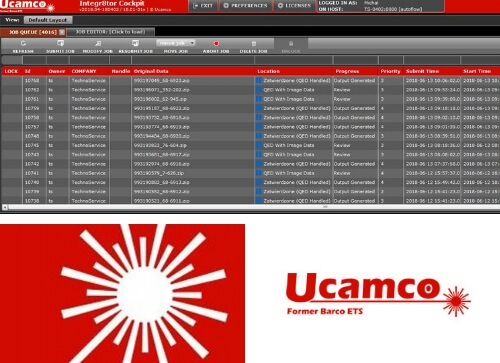
Machines (block B2), thanks to the interfaces (block B3), co – operate bi – directionally with the ERP. They provide data to the systems that in turn provide information to employees (blocks C1 and C2), including: the order in which the projects are to be implemented (Fig. 1a) and yields (Fig. 1b). Block C2 sends alerts which came from the machines and are occurring in other areas: traffic maintenance D1, monitoring of technological processes D3, as well as logistics and supply E2. The block C2 is also used for sending the information to clients. Then the necessary data is being collected from the ERP or CRM systems (block C3).

(a)

(b)
Fig. 1. Visualization of job queuing (a) and obtained performances (b).
Three systems are used to monitor the proper operation of the machine park and to maintain optimal process parameters: MP2 – maintenance, SCADA – control of production processes and data acquisition, and ELG – monitoring and supervision of technological processes.
The SCADA and the ELG are powered by a chain of sensors measuring directly specific physical quantities (temperature, pressure, media consumption, etc.) and complex parameters (block F3). The SCADA also controls processes through associated servos associated with e.g. valves, blowers, pumps and heaters. In addition to the ELG, measurement results (block F4) of specific parameters describing the chemical processes taking place in many baths are introduced, among others on the galvanic line, gilding line, etc. The system analyses the input data and suggests actions to properly maintain the technological parameters, e.g. by: adding appropriate chemical reagents to the bath or changing settings on the dosing devices.
The MP2 system is mainly used for: monitoring the condition of machinery and production equipment, planning and reporting preventive tasks, running a spare parts warehouse, along with automatic generation of spare parts orders, whenever their quantity falls below the minimum level. The MP2 also has fault prediction functionality, allowing it to counteract or minimize the effects of failures – especially those that may cause timing threats in the performance of the circuits.
Supplying the company with production materials is carried out by the block E2 and related warehouses.
The subsystems located there control the condition of materials, generate purchase orders and predict the demand for key raw materials: laminates, prepregs and copper foils; and for selected chemical agents: descriptive paints, anti – soldering masks, substances used for tinning, gilding and galvanic coppering of circuits.
To supply drills and milling machines with tools, dispensers (block E3) are used. Their software monitors the tool status and on this basis informs about the need to re – supplement the magazines. This system automatically generates orders for new tools, based on expenditures, and predicts the demand on the basis of drilling programs for projects accepted for implementation and located before the drilling and milling stages. This last functionality allows to keep production smooth by securing of the right amount of tools. For this task, the system takes into account the delivery times for individual goods, while minimizing the value of the warehouse and delivery costs. Shipments of manufactured circuits are supervised by the systems for monitoring the delivery firms, located in E1 block. This process generates feedback information for the needs of the ERP and the customers.
The block diagram omits some of the smaller systems and tools supporting production and ancillary processes. These include: systems for monitoring the ambient conditions (temperature, humidity) in the areas of film formation and storage as well as radiation of mosaics and masks, cost – controlling system, tools supporting processes in the HR and HR area (e.g. planning the work and the holidays) that are associated with the ERP.