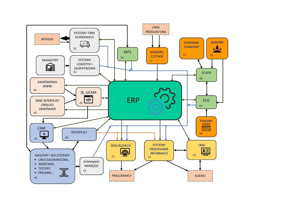
Integr8tor—project processing
The current capabilities of artificial intelligence, and above all machine learning techniques, combined with the high computing power of modern computers, allow you to analyse, search and classify information in large data streams.
The use of this potential for automated analysis of CAM documentation for printed circuit boards was proposed by the Belgian company Ucamco.
It is the world leader in the CAM software market for the PCB industry, as well as the creator of innovative technical and technological solutions, for example in the field of imaging the image of mosaics directly on laminates covered with photopolymer.
The Integr8tor software, created and being developed by Ucamco (abbreviated as I8), is a tool that automatically analyses CAM documentation of printed circuits in a highly autonomous manner. It extracts a wide range of technological parameters (including DRC), in order to prepare a cleaned set of files with uniform naming, which can be quickly used for further processing, in order to generate production documentation.
Project processing begins with its automatic loading.
Integr8tor recognises many input file formats (Extended Gerbers, X2 Gerbers, ODB++, BRD files, Excellon2, Sieb & Mayer, etc.).
Referral of the project to I8 can be implemented in several ways – both manually and with the use of integration: with a website, e-mail server or network filesystem. Integration with other systems allows you to automate the exchange of input and output data using scripts.
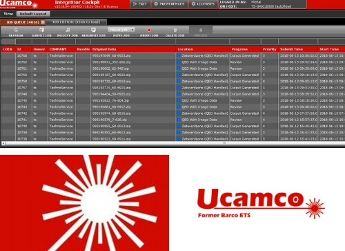
Projects processed by Integr8tor are visible in the list (fig. 1), together with information including among others: statuses, the time of adding to the list, the planned and the actual time of completion of the analysis.
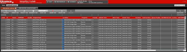
Fig. 1. View of the main window with a list of analysed projects.
By default projects are analysed starting with the earliest one added. The processing order can be changed by prioritising them. This function is useful when processing projects with different degrees of urgency. After adding the project to the analysis, the I8 indicates the estimated start and end time, which facilitates work planning.
After loading the project, the use of layers is made using the entries in the names of layer files, comments from CAM files, information from other files attached to the project, as well as on the basis of images stored on individual layers. Mosaic layers should have a function assigned Outer or Inner respectively, for external and internal layers, and the given position, starting with 1 for the Top copper layer, etc. Layers of anti-soldering masks and descriptions function Soldermask and Legend. The layer's location page is declared as Top or Bottom.
Although the classification takes place automatically, it is possible to modify the assigned types later. We have around 30 different functions to choose from (Fig. 2), thanks to which each layer can be properly classified and the project properly analysed.
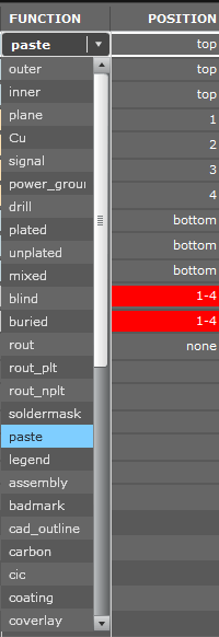
Fig. 2. Window for editing layers' functions and positions.
When I8 has doubts about the assigned layer/position, warnings or fatal errors are displayed, depending on the scale of the problem. Layers affected by the problem are highlighted in yellow for comments or in red for critical errors (Fig. 3).
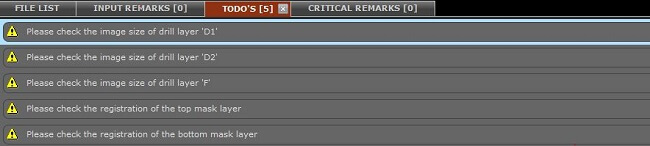
Fig. 3 Widow of errors.
In the process of recognizing layers, I8 also uses the knowledge base, which the program builds on the basis of correct analyses accepted by the operator, i.e. in the supervised learning process. This is undoubtedly a great advantage of the software, because as the number of analysed projects increases, the number of false errors in classification of layers decreases, which streamlines the analysis process and increases its autonomy.
In the next processing step, the most important technological parameters of the project are determined. Due to their size, selected properties will be listed. In addition to the mentioned DRC parameters, the software analyses the layers of anti-soldering masks, SMD elements, and for BGA systems determines the raster. In addition, the surfaces of copper exposures and the area to be covered by the anti-soldering mask are calculated.
The layers of mechanical treatment – drilling, milling, scoring, etc. – are also examined in depth. In addition to matching holes for mosaics or unveiling on anti-soldering masks, I8 recognizes whether the holes are metallised or non-metallised. The values of minimum and maximum diameters, along with the density of holes, the number of tools and holes, as well as the minimum distances between individual drilling are determined. The software automatically detects blind and buried guides.
At the end of processing, Integr8tor creates a report file in PDF and XML formats, containing the found technological parameters of the project, and generates the resulting, cleaned project files in DPF format with a uniform name. In these collections, the areas of masses outlined by paths are contoured, and the pads painted with paths are replaced with dedicated apertures of the same size and shape as in the original.
In order to increase the flexibility and to integrate the I8 in the internal processes and circulation of the PCB manufacturer's documentation, it is equipped with the BeanShell script language, based on Java.
In TS PCB scripts are used for efficient implementation of data exchange between the Integrator and the ERP system and to improve the circulation of files with documentation.