How to optimize machining of printed circuits? - part 1

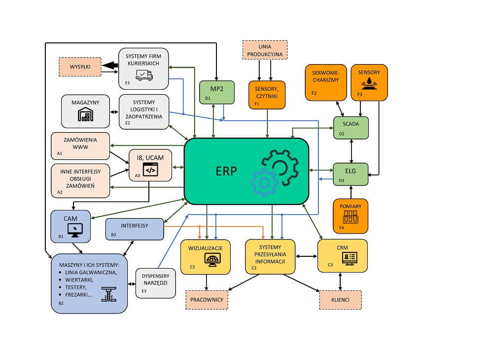
The final stage of the printed circuits production is machining.
They reach its final shape during milling and scoring process. Improperly designed machining can distinctly increase the production costs and extend the awaiting time for delivery of the final product, especially in case of orders covering large scale production.
In the first part of this article we present detailed information about machining of the printed circuit boards with use of milling and scoring. In further part, we list those parameters which are characteristic for both methods.
Machining types
The most common methods of machining of the printed circuits, used in TS PCB also, are scoring and milling. Those processes are performed on a CNC numerical processing machines.
Scoring of circuits edges relays on cutting a laminate with a high-speed circular knife in result of which the grove is created allowing for breaking plates from a production format or a panel for automatic assembly (pic. 1). Although many restrictions this is still the cheapest way allowing for shaping the circuit contour.
One of the basic limits of the process is the shape of the board, because scoring can be used only in case of boards of a rectangular shape because scoring machines are moving only in horizontal and vertical directions. This means that in such machining boards of e.g. circular shape cannot be used, because they have to have only straight edges. Moreover, circuits on thin laminates, i.e. of thickness lower than 0.5mm cannot be scored. In turn for laminates of thickness of 2.4 mm and thicker manual separation of circuits can be a problem due to a necessity to apply a big force.
Basic disadvantages of scoring are: poor quality of edges which are not rectangular in a cross section and relatively big dimensional tolerance of circuits which in the best case is ±0.1 mm. Compared to milling this translates to a wider spread of the final dimensions of scored circuits.
Milling, during which the final shape of the circuits is formed with use of a tool (cutter) rotating around it axle and moving with linear motion (pic. 2) in turn is deprived of many of its disadvantages and restrictions. Milling-cutters have circular cross section and their diameter most often is contained in the range from 0.6 mm to 2.4 mm.
Almost any shapes of boards can be milled: circular and having cut-ins on the edge. Wide variety of a laminate thickness is also allowed in the process. It only restriction is rounding of the cut-outs internal angles resulting from the diameter of the used tool. Milling allows to achieve very good quality of the circuit edge and also characterizes with almost double narrower dimensional tolerance (compared to scoring) at the level of ±0.05 mm. Achieving high quality of machining is possible thanks to use of a basing mechanism of a CNC milling machine on punching or mosaics of circuits in order to compensate it real arrangement.

Pic. 1. Production format fitted in the CNC scoring machine

Pic. 2. Machining in the CNC milling machine