Testing printed circuits: Blade testers
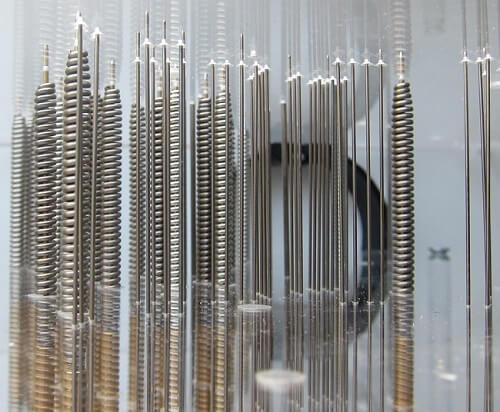
In contrast to testers with moving probes which have a small number of measuring heads (usually 4), in the blade testers a significant number of fixed measuring probes are used in the form of needles of different diameters (fig.1). The diameters of the needles match the contact surface area of the test points of the printed circuit on which stiff needles with a diameter up to 1.8 mm are used whereas above this limit needles equipped with additional springs are used, improving elasticity.

(a)

(b)
Fig. 1. Different types of needles visible from the printed circuit side (a) and between the adapter plates (b).
The needles provide an electrical connection between selected PCB test points and the so-called tester cassette which is a matrix of the measuring system sockets arranged with a fixed raster. Its size determines the working field area of the blade tester, and so the maximum size of the circuit that can be tested. In simple single-sided needle testers, there is a single lower cassette which forms the base for the adapter fitting. This design allows the printed circuit to be tested from one side. More advanced testers are equipped with two cassettes and can use two adapters so they can test both sides of the circuit simultaneously.
The most popular raster of cassette socket is 100 mils (2.54 mm), which allows the use of approximately 16 needles and measuring channels on 1 cm2 of the PCB surface area. Depending on the device class, the cassette raster may be denser and amount to 70 mils (about 1.78 mm) or even 50 mils (1.27 mm) giving the possibility to cast about 23 and 62 needles and measuring channels per 1 cm2 of the printed circuit surface area.
To ensure correct and steady arrangement of the needle probes in relation to the printed circuit board while also ensuring good electrical contact between the needles and the circuit test points and cassette seats, it is necessary to use an adapter or a fixture (fig.2).
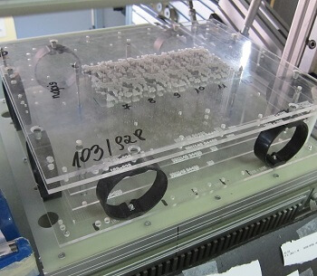
Fig. 2. An example of an adapter mounted on the lower cassette in the tester chamber.
The adapter construction
An example of a single sided adapter is presented in fig.3. It contains four plates made from plexiglass (PMMA) of specified thicknesses. The plates are flush with each other so that, thanks to elasticity of the needles, according to the layout of the printed circuit test points to the closest cassette sockets. Correct adjustment to the cassette raster forces the bottom plate of the adapter to be perforated. The needles can freely move vertically and slide into the cassette sockets to provide electrical contact. Achieving good electrical contact requires the application of pressure between the tested circuit and the adapter and cassette.
In a single-sided tester, the pressure is realized by a moving table and in a double-sided tester by a moving upper cassette. Those elements are usually driven by a pneumatic servomotor through a lever system that regulates the contact pressure.
.png)
Fig. 3. A single-sided adapter cross section for the cassette with a 100 mils raster with a description of the components.
The adapter design process is carried out with the use of dedicated software and is the preparatory stage preceding the actual testing. It lasts longer than the development of a program for testing the finger tester for the same circuit. The software based on the netlist and the arrangement of the external mosaics (and thus the test points) of the circuit in relation to the cassette socket raster selects the location coordinates and the types of needle probes.
In case of the SMD systems with dense soldering fields, the staggering technique is used. The program also arranges additional elements such as conical pins based on a printed circuit board in relation to the adapter and various types of brackets to ensure the correct rigidity of the entire structure in the horizontal plane and, at the same time, elasticity in the vertical direction. At the end of the design process, the following are generated:
1. a program for the blade tester specifying the cassette sockets that will be the measuring points probed with needles,
2. the CNC drilling programs necessary to make holes in the PMMA boards – the main adapter components,
3. assembly documentation.
Based on this documentation, a qualified professional mounts the individual adapter components into a uniform structure. This is a time-consuming process in which the need to fill the adapter with needles is the most arduous. Depending on the number of needles, assembling a single-sided adapter can take up to 1 hour and a double-sided adapter may take twice as long. For this reason, to reduce the time required to test projects that are often duplicated, the PCB manufacturers store their adapters in an assembled form. The rest of adapters are archived for some time in a disassembled form.
Testing procedure
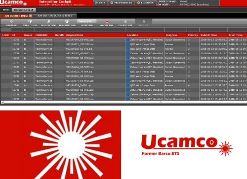
The correct testing procedure consists in mounting the adapters of the tested project in the tester cassettes according to the base pins and uploading the test program or teaching the tester the standard structure of the electrical networks by using the so-called golden board. Then a repeatable sequence of following operations takes place: mounting in accordance with the base pins, the circuit/panel in the lower adapter, pressing the upper tester cassette during which the correct test is performed for all the tested networks and damage classification, removing the tested circuit from the tester. After lifting the upper cassette, the test result appears on the attached monitor and if any irregularities are detected, feedback is generated for the repair station.
The testing procedure uses a considerable number of measuring paths for the blade tester.
For an example double-sided tester with a working area of 25.6 x 19.2 inches and a 70 mils raster, it is almost 200,000.
Such significant number of tester measuring paths —w hich on the one hand indicates the immense complexity of the system and the development of the entire measuring block (fig.4) and damage classification — is also the essential advantage of this testing technique because it allows continuity and insulation tests to be conducted on multiple networks simultaneously. Such concurrency reduces the testing time to mere seconds which is incomparably shorter than testing the same circuit on the finger tester. The performance of adapter testing can reach up to a few thousands test points per second regardless of the distribution of test points. For comparison, finger testers achieve a similar number of test points per minute but their performance depends on the distribution of the test points.
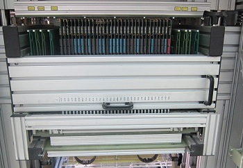
Fig. 4. Measuring paths of the upper cassette located on vertically mounted measuring cards.
The short testing time ensures a high testing efficiency which can be even up 5 times greater than for the finger tester. For this reason, blade testers are used for the electrical testing of a large-scale production run of printed circuits. Because more time is required for the preparation stage during which the testing program is developed and the adapter is made and assembled, there is a minimum number of production formats above which the adapter testing becomes much more efficient from the finger one. Usually the needle test profitability limit is a dozen or so production formats.
Companies producing blade testers offer additional techniques to increase the testing efficiency. More often than not, however, these are hardware solutions including automated systems for loading and unloading circuits (fig.5). This is due to the fact that the manual loading and unloading of a single circuit lasts longer than the actual testing stage. The second direction of performance optimization is to increase the tester’s working surface to allow for the adapter testing of entire production formats.
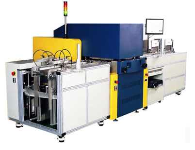
Fig. 5. Mason blade testers with the automatic loading and unloading of circuits