Testing printed circuits: Electrical testing – testers with moving probes
The operation rule of those type testers, also called finger ones, relays on performing measurements with use of measuring heads equipped in probes moving on both sides of the stationary fixed printed circuit (pic. 1a). In the most popular configuration the tester is disposing four resistance measurement channels connected with four independent probes (pic. 1b), two on each side of the board. An advantage of a small number of measuring channels is possibility of easy expansion of their functionality.
The most popular equipment attachments are offering among others the measurement of very small resistances with use of the Kelvin clamps, transmission lines impedance examination and the isolation leakage with the high voltage excitation amounting to hundreds of volts (HiPot testing).
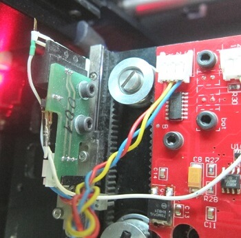
(a)
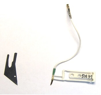
(b)
Pic. 1. The finger tester head equipped in the probe (a) and the most popular types of used probes (b).
The most important mechanical parameters of the fingertester are conditioned mainly by servomechanisms properties responsible for moving the probes. They are characterizing with high speed and high precision guarantying repeatedly positioning of the measuring probes in X and Y axes with the step at the level of 0,5 mils, or even less, which allows for their precise hitting in small and densely located pads e.g. SMD microcircuits. The mechanical assembly parameters are conditioning to lower limit of pads, minimal distance between adjacent test points and are responsible for the pressing force of the probes to the pads. Those and other parameters of the typical finger tester are presented in the tab. 1.
|
Parameter |
Value |
|
Probes moving raster (X and Y axis) |
±0.5 mils / ±12.7 µm |
|
Min. pad dimension |
4 mils / 101.6 µm |
|
Min. distance between adjacent testing points |
8 mils / 203.2 µm |
|
Probes pressure to testing points |
5÷20 g |
|
Allowed thickness of tested circuits |
0.2÷3.2 m |
Tab. 1. Mechanical parameters of a typical finger tester.
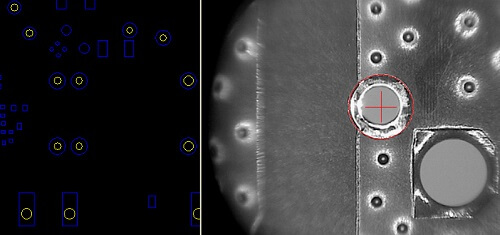
To maintain possibly the highest repeatability of the probes hitting test points it is necessary to precisely base (board registration) the mechanics in relation to reference points distributed at the ends of the tested production format. This process is eased by CCD cameras, one on each side of the circuit, giving enlarged picture of the circuit fragments surrounded by real reference points. On those pictures the contours of next pads are overlaid which were defined in the test program as reference points. The basing operation was presented on pic. 2, where the left picture presents the circuit fragment with plotted location of the reference point, and the right one is the real image of the circuit on which the reference point location and corresponding it pad were matched.
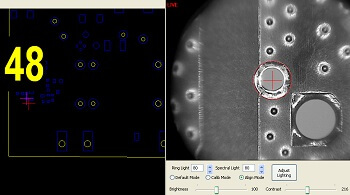
Pic. 2. Registering the tester on the reference point.
Speeds and accelerations of the servomechanisms directly influence the testing speed expressed in testing points number per minute and test time resulting from it. For the exemplary tester from Ultim8 family by Mania company the testing speed reaches 5 thousand points per minute. Not without significance for the tester speed is also the tester software which optimizes movements sequences of individual probes in such way to minimize necessity of frequent relocating them by larger distances.


